Top Oil Separator Types for Global Buyers?

Choosing the right Oil Separator is rarely a simple catalogue decision. Global buyers face different flow rates, oil densities, temperatures, solids, and discharge expectations. A gravity separator may suit a steady workshop stream. A coalescing separator can provide finer oil removal. Hydrocyclones and centrifugal units may handle compact installations or demanding process conditions. Each design has a place. None is universal.

Dr. James R. Fair, a respected separation-process authority, stated, “Separation equipment must be selected from process conditions, not from appearance.” That principle remains practical for international purchasing teams. A polished stainless-steel unit may look impressive, yet poor sizing can create carryover, pressure loss, or frequent cleaning. Buyers should review hydraulic capacity, residence time, oil viscosity, corrosion resistance, maintenance access, and verified test data. Supplier experience also matters. Ask for performance results using similar wastewater, not only laboratory water.

The details are physical and easy to overlook. Picture a separator receiving warm water, floating oil, sand, and sudden flow surges after a storm. A small inlet chamber may disturb the separation zone. A weak drain arrangement may leave oil trapped inside. I would not pretend that one specification sheet answers every question. Site sampling is better, although it can be inconvenient and imperfect. Reliable suppliers explain these limits clearly. They also provide drawings, operating instructions, spare-parts guidance, and realistic removal claims. For global buyers, the strongest choice balances separation performance, total ownership cost, local service, and long-term reliability. Sometimes, the cheapest unit is the most expensive mistake.
Top Oil Separator Types for Global Buyers?

Oil Separator Fundamentals: 15–150 mg/L Discharge Targets and 50–300 μm Droplets

Top Oil Separator Types for Global Buyers?

Oil separator performance depends on droplet size, flow variation, temperature, and oil density. API Publication 421 uses about 150 μm oil droplets as a practical reference for gravity separator design. Larger droplets rise more easily. Smaller droplets need coalescing media, longer retention, or polishing treatment.

The 50–300 μm range covers several separation challenges. Droplets near 300 μm may separate through gravity chambers. Droplets near 50 μm often require coalescing plates or advanced treatment. Field testing should confirm actual influent conditions, because laboratory water rarely matches a busy workshop or industrial drain.

It gets messy.

A 15–150 mg/L discharge target must be treated as a project criterion, not a universal global limit. US EPA Method 1664 measures oil and grease, while ISO 9377-2 measures hydrocarbon index; these methods can produce different reporting results. Buyers should request test conditions, sampling points, retention time, and influent oil concentration.

A separator rated at 15 mg/L may fail during peak flow or emulsified contamination.

That limitation deserves attention.

Performance claims also need independent verification under representative conditions, with maintenance access, sludge capacity, and alarm requirements included in the specification.

Gravity API Separators: 150–300 μm Droplet Removal Under API RP 421

Gravity API separators remain a practical choice for removing free oil droplets from industrial wastewater. Under API RP 421 guidance, properly designed units can target droplets around 150–300 μm. They rely on density differences, low turbulence, and adequate residence time rather than mechanical energy.

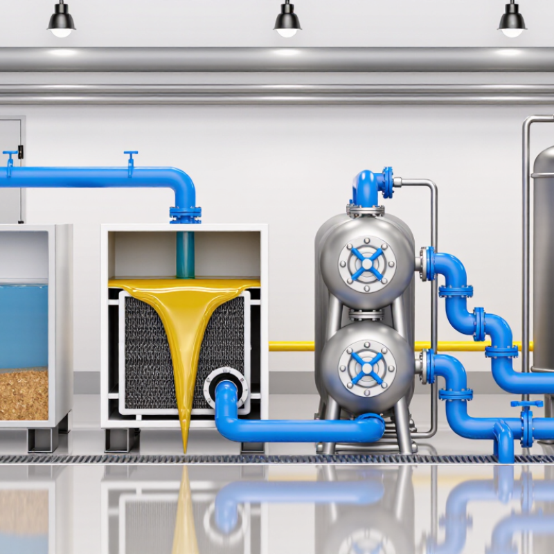
Inside the separator, influent enters a calmer zone where oil droplets rise toward the surface. Sludge settles below, while treated water exits through an outlet section. Plate packs or coalescing features may improve separation, but they require careful fouling control. Flow distribution matters greatly. A short-circuiting channel can reduce performance, even when the tank volume appears sufficient.

Field experience shows that temperature, viscosity, emulsions, and sudden flow changes affect removal efficiency. Small droplets need more time. Not every site behaves neatly. Designers should verify hydraulic loading, surface loading rate, retention time, and freeboard using actual wastewater data. Sampling before and after commissioning provides stronger evidence than calculations alone. Operators should also inspect oil-skimming equipment, sludge depth, inlet screens, and outlet weirs regularly.

A separator sized only for average flow may struggle during stormwater events or production changes. That weakness is easy to overlook. Influent testing should include oil concentration, droplet distribution, temperature, and suspended solids. API RP 421 offers a sound design framework, but site conditions still require engineering judgment and ongoing review.

Coalescing Plate Separators: 50–150 μm Droplets in Compact Tanks

Top Oil Separator Types for Global Buyers?
Coalescing plate separators are designed for free oil droplets around 50–150 μm. Their inclined plates create more settling area inside a compact tank. API Publication 421 identifies 150 μm as a common gravity-separation design reference. Coalescing media can improve performance, but feed conditions remain decisive. Oil viscosity, density difference, temperature, turbulence, and solids loading all affect removal. A small tank is not automatically a high-performance tank.
Field commissioning often reveals the weak point: poor inlet distribution. One short-circuiting flow path can reduce actual separation sharply. The US EPA’s industrial stormwater guidance commonly uses 15 mg/L oil and grease as a benchmark, although permit limits vary by sector and location. Buyers should treat that figure as a verification target, not a universal guarantee. Ask for test conditions, droplet-size assumptions, hydraulic loading, and outlet sampling methods. A stated “50 μm rating” needs evidence.
Tips: Request a removable sludge zone and accessible plate packs. Check the design at the lowest operating temperature. Confirm whether the quoted flow is continuous or peak flow. Include an upstream screen when solids are expected. I would also question any brochure promising identical results for light fuel oil, heavy lubricants, and emulsified wastewater. Those fluids behave differently. Modest claims are often more useful.

Hydrocyclone Separators: 10–30 μm Cut Points for High-Flow Applications

Hydrocyclone separators suit high-flow oil treatment when compact equipment and steady operation matter. They use centrifugal force, not filter media, to separate oil droplets or suspended solids from a liquid stream. A correctly designed unit can target cut points from 10 to 30 μm. Flow remains continuous, and there are no rotating parts to maintain.

A 10 μm cut point demands careful control. Feed pressure, viscosity, density difference, droplet shape, and inlet geometry all affect separation. Higher pressure may improve performance, but it also increases energy use and wear. For a 30 μm target, operators often gain easier handling and stronger flow capacity. The choice should follow actual fluid tests, not a catalog number.

Field checks are essential. Measure inlet and outlet oil concentration, pressure drop, temperature, and flow stability. A 20 μm rating is not an absolute promise. I have seen systems underperform when cold oil became too viscous or when droplets entered too finely dispersed. That detail is easy to miss. Global buyers should request test conditions, expected removal efficiency, materials, drainage design, and maintenance guidance. A pilot trial may cost time, yet it can expose weak assumptions before full-scale installation.

Top Oil Separator Types for Global Buyers? - Hydrocyclone Separators: 10–30 μm Cut Points for High-Flow Applications
Hydrocyclone Configuration Typical Liquid Service Nominal Oil-Droplet Cut Point, d50 Typical Flow per Liner Typical Feed Pressure Typical Pressure Drop Oil-in-Water Performance Key Selection Considerations
Compact deoiling hydrocyclone Produced water with relatively low to moderate oil loading 20–30 μm 5–25 m³/h 6–12 bar 3–6 bar Commonly used as a polishing step; final oil concentration depends strongly on droplet-size distribution and feed chemistry Suitable where installation space is limited and a stable feed pressure is available
High-flow parallel-liner bank Large produced-water streams from offshore and onshore separation systems 15–30 μm 20–100 m³/h 8–15 bar 4–8 bar Provides high aggregate throughput by operating multiple liners in parallel Allows capacity expansion and maintenance of individual liners without shutting down the complete bank
Fine-cut hydrocyclone Relatively clean water requiring additional removal of small dispersed oil droplets 10–20 μm 3–20 m³/h 8–16 bar 5–10 bar Can improve removal of smaller droplets when sufficient pressure differential and suitable feed conditions are maintained More sensitive to viscosity, solids, emulsion stability, and insufficient inlet pressure than coarse-cut designs
Wear-resistant ceramic-lined unit Produced water containing abrasive sand or mineral solids 15–30 μm 5–40 m³/h 8–16 bar 4–9 bar Oil separation performance is comparable to the selected hydraulic geometry; lining primarily supports service life Consider when solids concentration, particle hardness, and erosion risk are higher than normal
Multistage hydrocyclone system Water streams requiring staged removal of free oil and smaller dispersed droplets 10–30 μm per stage 10–80 m³/h total 10–18 bar 6–12 bar total Can provide improved overall treatment by combining separate hydraulic stages with intermediate monitoring Requires more instrumentation, balancing, space, and control of cumulative pressure loss
Low-shear hydrocyclone arrangement Water containing shear-sensitive oil droplets or partially stabilized dispersions 20–30 μm 5–30 m³/h 6–12 bar 3–7 bar Designed to limit unnecessary droplet breakup; separation remains dependent on fluid properties and residence conditions Useful when avoiding additional emulsification is more important than achieving the smallest possible cut point
Engineering reference ranges only. Actual hydrocyclone performance varies with oil density, water density, viscosity, temperature, salinity, oil loading, solids content, droplet-size distribution, inlet pressure, and the required water-quality target. The d50 value represents the approximate droplet diameter at which separation efficiency is 50% under defined test conditions; it is not a guaranteed minimum removal size.

Global Selection Criteria: EN 858, API RP 421, Flow Rate, and Oil Density

Top Oil Separator Types for Global Buyers?

Global buyers should begin with compliance, not catalogue size. EN 858-1 separates systems into Class I and Class II performance. Under standard test conditions, Class I units target hydrocarbons below 5 mg/L, while Class II units allow up to 100 mg/L. These figures are useful, but they do not represent every site. Actual results depend on turbulence, maintenance, temperature, and emulsified oil.

Flow rate is the harder decision. API RP 421 recommends evaluating peak inflow, retention time, droplet size, and separator geometry. A unit designed for 20 L/s may fail during a short 35 L/s storm surge.

Rainfall intensity data should come from the local drainage authority, not a convenient online calculator. That difference matters. Oversizing can reduce velocity, yet excessive volume may increase sludge accumulation and maintenance costs.

Oil density also changes selection. Engineering references commonly place mineral oil near 0.80–0.95 g/cm³ at 15°C, compared with water near 1.00 g/cm³. The smaller the density difference, the slower separation becomes. Free oil usually suits gravity separators, while stable emulsions may require additional treatment. This distinction is often missed. Buyers should request test certificates, hydraulic calculations, access dimensions, alarm specifications, and cleaning records. EN 858-2 also emphasizes installation, operation, and maintenance. A technically compliant separator can still underperform when its coalescing elements remain blocked. Industry guidance is valuable, but site measurements should challenge assumptions.

Article Source:

Contact Us Today for a Free Quote

(800) 708-6036