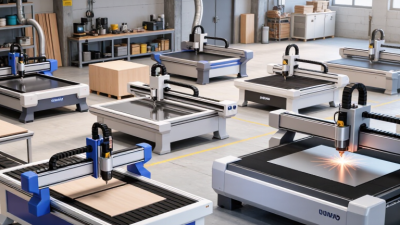
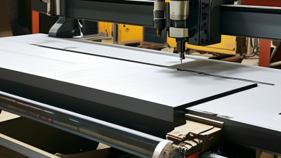
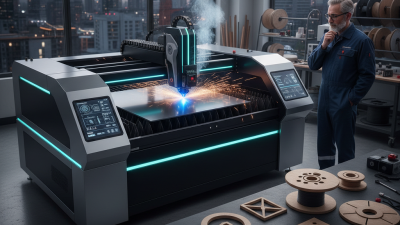
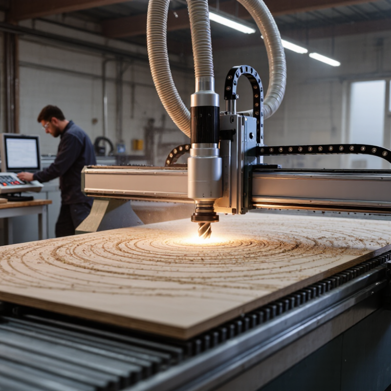
CNC cutting converts a digital design into a physical part by guiding a cutting tool along programmed paths. The term covers several processes, including CNC routing, laser cutting, plasma cutting, and waterjet cutting. Each method removes material differently, so machine choice depends on the material, its thickness, required edge quality, and production needs. Picture a plywood panel secured beneath a router: the bit follows an outline while dust extraction helps keep the work area clear. Small details matter. A loose sheet or unsuitable feed rate can affect the edge, dimensions, or tool life.
Most jobs begin with a CAD drawing, which is prepared for machining through CAM software. The software creates instructions that control the tool’s movement, speed, and cutting sequence. An operator then checks the material, secures it, sets the machine, and verifies the first cut. That check can reveal problems a screen preview misses. CNC cutting offers repeatable results, but it does not make every part automatically accurate; setup, tool condition, and material variation still matter. The process can look effortless from outside the workshop. In practice, careful planning and inspection make the difference between a clean profile and a part that needs rework.
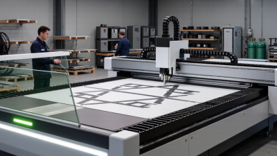
CNC cutting is the removal or separation of material using machine movements directed by a computer-controlled program. CNC means computer numerical control. The program converts a digital design into toolpaths, which guide a cutter, laser, plasma torch, or waterjet along selected axes. The machine can cut sheet metal, plastic, wood, and other materials, depending on its tooling and settings. A flat metal sheet may become a bracket after the cutting head follows its outline and pierces marked holes. Small details matter: tool choice, material thickness, and workpiece positioning all affect the result. Not magic.
The process usually begins with a CAD drawing, then a CAM system prepares machine instructions. An operator checks the setup, secures the material, and runs the job. Sensors and machine controls help manage movement, but they cannot fix a flawed drawing or poor setup. Grand View Research estimated the global CNC machine market at USD 101.2 billion in 2023, with a projected 9.5% compound annual growth rate from 2024 to 2030. This market estimate covers CNC machines broadly, not cutting alone. That distinction matters. CNC cutting can improve repeatability, yet actual tolerances vary with the machine, material, maintenance, and process. Even a clean edge may need deburring. The practical question is not only what the machine can cut, but how consistently it can meet the drawing’s requirements.
A CNC cutting system is a group of parts that turns a digital design into controlled machine movement. The controller reads programmed instructions and coordinates the cutting head, motors, and other machine functions. Motion components, such as rails and drive screws, guide the head across the material. They need to stay aligned; even small mechanical play can leave a visible edge defect.
The cutting head depends on the process. It may hold a router bit, laser, plasma torch, or waterjet nozzle. A frame supports the machine, while a bed or fixture holds the workpiece in place. Clamps must secure the sheet without blocking the cutting path. The setup is rarely as tidy as a diagram suggests. A slightly warped sheet can shift during cutting.
Software is another essential component. Design software defines the shape, while CAM software turns it into a toolpath with speeds, directions, and cut settings. The controller follows that path, often using feedback from sensors to track position or detect faults. Operators still need to check material thickness, tool condition, and extraction or cooling systems before a job. Small details matter. A clean nozzle or sharp bit can improve the cut, though settings may need adjustment after a test piece.
A CNC cutting job starts with a digital drawing, often made from lines, curves, and measured dimensions. The designer specifies the part’s shape and material thickness. Small details matter. A narrow slot may need extra clearance because the cutter removes material as it moves. That removed strip is called the kerf. If the drawing ignores it, parts can come out too small.
CAM software turns the drawing into toolpaths: instructions for where the cutting tool travels, how fast it moves, and when it starts or stops. The operator selects settings for the material and cutter, then generates machine-readable code through a suitable postprocessor. Before cutting, the program can be checked in a simulation. This may reveal collisions, missed contours, or an inefficient route. Not always. A digital preview is useful, but it cannot perfectly represent a warped sheet or a tool that has worn down. The material must be secured, the machine’s starting point set, and key dimensions checked against the drawing. One small setup error can shift the entire cut. After a test piece, measured results may lead to adjustments in the design or cutting settings.
A CNC cut begins with a digital toolpath that tells the machine where to move and how fast. The controller translates those instructions into coordinated axis motion. Meanwhile, a spindle rotates the cutter, and the programmed feed rate advances it through the material. The cutter removes thin chips; the workpiece stays clamped to the table. A loose clamp can spoil the cut.
For a milling pass, feed rate depends on spindle speed, the cutter’s number of teeth, and feed per tooth. Operators check these values against the material and tool, then watch for chatter, heat, and chip shape. Small details matter. ISO 230-2:2014 specifies tests for positioning accuracy and repeatability on numerically controlled machine axes. Its test records compare commanded positions with measured movement, helping distinguish a toolpath problem from axis error. ASME B5.54 also provides methods for evaluating CNC machining-center performance. Still, a clean test result cannot guarantee every part will match the drawing: tool wear, vibration, and workholding can shift the cut. The edge may look smooth. Measure it.
Typical carbide milling cutting-speed ranges by material
A CNC machine follows programmed toolpaths to move a cutting tool and remove material in controlled passes. Cutting speed is the speed at which the tool edge moves across the material. The ranges shown are broad typical starting points for carbide milling; the appropriate value depends on the tool, workpiece, machine rigidity, and cutting conditions.
What Is CNC Cutting and How Does It Work?
Common CNC Cutting Methods and Materials
CNC cutting uses programmed toolpaths to remove or separate material with controlled motion. Milling uses a rotating cutter across a fixed workpiece; turning spins the workpiece against a cutting tool. Drilling makes round holes. For sheet materials, laser, plasma, and waterjet cutting are common choices. A waterjet avoids a heat-affected edge, while laser cutting can leave heat discoloration. A clean cut is not always a finished part.
Material choice affects the method, tool, and final edge. Aluminum is light and machines readily, but thin sections can vibrate or bend. Steel is tougher and may need slower cutting and stronger tooling. The World Steel Association’s World Steel in Figures 2024 reports 1,888.2 million tonnes of global crude steel production in 2023, showing steel’s vast role in manufacturing. Plastics can melt if tools run too hot; wood may chip along the grain. Small details matter.
Tips: Match the cutting method to the material thickness and required edge quality. Secure thin stock firmly, and check the first cut before running a full batch. Tool settings that work on paper may still need adjustment on the machine.
| CNC Cutting Method | How It Works | Common Materials | Typical Uses | Key Considerations |
|---|---|---|---|---|
| CNC Milling and Routing | A computer-controlled rotating cutting tool removes material along programmed paths. Milling machines commonly handle rigid workpieces; CNC routers are often used for larger sheets. | Aluminum, steel, brass, wood, plywood, plastics, and some composites | Slots, pockets, profiles, contours, and 3D features in parts or sheet goods | Tool choice, cutting speed, workholding, and material properties affect finish and accuracy. Cutting tools wear during use. |
| CNC Laser Cutting | A focused laser beam melts, burns, or vaporizes material along a programmed path, usually with assist gas. | Carbon steel, stainless steel, aluminum, and selected plastics or wood, depending on the laser and setup | Detailed profiles, sheet-metal parts, signage, and thin-sheet components | Material type and thickness determine suitable laser power and edge quality. Some plastics can release hazardous fumes and require appropriate controls. |
| CNC Plasma Cutting | An electrically conductive gas is heated into plasma, which melts metal while a gas stream removes the molten material. | Conductive metals, especially mild steel, stainless steel, and aluminum | Plate profiles, brackets, frames, and heavy-duty metal components | Generally suited to thicker conductive sheet and plate. The cut edge may have more taper or heat-affected material than precision laser or waterjet cutting. |
| CNC Waterjet Cutting | A high-pressure water stream, often mixed with abrasive, erodes material along a programmed path without a heat-based cutting process. | Metals, stone, glass, ceramics, rubber, foam, and composites | Thick or heat-sensitive materials, intricate profiles, and mixed-material jobs | Because it introduces little heat, thermal distortion is limited. Cutting speed and edge finish depend on material, thickness, pressure, and abrasive use. |
| CNC Wire EDM | A thin, electrically charged wire removes conductive material through controlled electrical discharges while the workpiece is immersed in dielectric fluid. | Conductive metals, including tool steel, stainless steel, and titanium alloys | Precision profiles, narrow slots, punches, dies, and hardened components | Only electrically conductive materials can be cut. The process is typically slower than many mechanical methods but can produce intricate shapes and fine features. |
How CNC cutting works: A digital design is converted into machine instructions, which guide the cutting tool or energy source along a programmed path. The best method depends on the material, thickness, required geometry, edge finish, and production needs.